Quiz Buzzer System
July 9, 2023
VIDEO
The Quiz Buzzer System is a robust and unique system that is being used by QuizWorks India and QuizCraft India, companies providing quizzing services all over India. A maximum of eight teams can be supported by this buzzer system. It consists of a large 7-segment display which shows the buzzing team number.
This buzzer system is capable of recording the buzz sequence and displaying it in case there is a contention for buzz on a particular question. The sound output from the buzzer is in MONO. A stereo or a mono 3.5 mm TRS connector from an amplifier/media system can be connected to it.
Buzzer package contents
The buzzer package that was shipped to QuizWorks contained the following items:
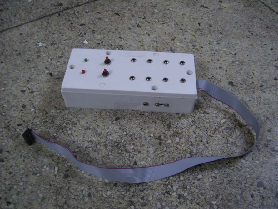
- 1 Main Control Box
- 1 AC 220V to DC 12V 2A wall adapter
- 1 large 7 segment LED array display
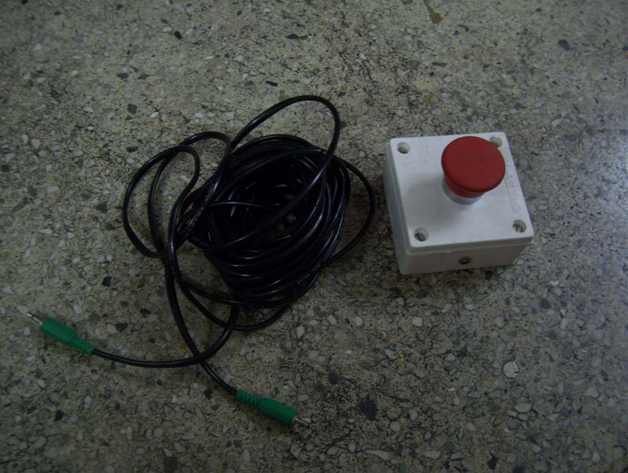
- 8 buzzers
- 8 connection cables of length 8.1 m (approx.)
And the system that was shipped to QuizCraft contained a slightly different set of items:
- 1 Main Control Box
- 1 Power cable
- 1 large 7 segment LED array display
- 10 buzzers
- 10 connection cables of length 10 m and 5 extension cables of length 10 m for larger venues
Design and Construction
The buzzer system has been designed keeping in mind the needs of the quizzing fraternity. Therefore, standard and robust buzzers were designed using industrial grade mushroom headed pushbutton switches (used in fire alarm systems). The encapsulating boxes are essentially plastic electrical switch boxes. Accompanying connection cables of length approximately 8.1 m and 10 m were provided.
The seven segment LED array display was made using seven LED array segments. The individual arrays were driven using seven IRF540 MOSFET transistors. The power and the signals to the LED display was supplied using a 16 pin FRC cable.
The seven segment display demonstration video (the two LEDs glowing in the video are because of a broken IRF540. It was replaced later on and it was working fine) –
The main circuit box consists of the control circuit which captures the buzzes from the individual buzzers according to the order of their occurrence. It contains an ATMEL ATMega8 microcontroller which keeps on polling all of the eight buzzer input pins to check for buzzes. As soon as a buzzer is pressed, it registers the buzz and looks for more buzzes. After the first buzz, it signals the LED display to show the team number that buzzed and emits a buzzing sound from it’s sound output. If there is a contention for a buzz, then there is a green LED to indicate the contention. The contention switch browses through all the teams that buzzed in their sequential order of buzz and the reset switch resets the buzzer system to its start state.
Risks associated with the system
The risk associated with this system is not significant as it does not deal with any substantial voltage or current level. Also, it is advised not to plug in headphones/earphones into the audio jack.
The buzzer system has been and is still being used at various quizzes across India by QuizWorks India and QuizCraft India without any report of malfunctions.