Motor Driver using MOSFETs
July 9, 2023
An H Bridge is a circuit that allows the application of a voltage on either ends of a load. One of the most important and primary use of this is in driving DC motors in varied applications. H Bridges are available as ICs (L293D, L298), or they can be built using individual components. A basic structure of an H-bridge is given below –
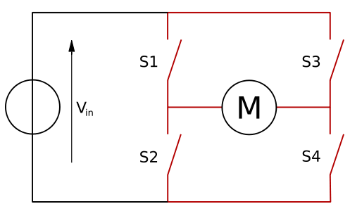
S1, S2, S3 and S4 are the four switches which can be selectively turned on/off to allow the flow of current across the motor in either direction. S1 & S4 on will give one configuration, and similarly S2 & S3 on will give the reverse.
The motor drivers which are generally available on the market are of industrial grade and hence, costly as they include a lot of features including safety. For most university projects, most of the features are not used and hence it becomes a waste of money to go for industrial grade motor drivers. One can make motor drivers for running powerful motors by using readily available and high power MOSFET transistors.
Making an H-Bridge
To make an H-Bridge, the following components are needed –
- 2 × 100 kΩ resistors
- 2 × 1 kΩ resistors
- 4 × 1N4007 diodes
- 2 × BC547 BJTs
- 2 × IRF530/IRF540 MOSFETs
- 2 × IRF9530/IRF9540 MOSFETs
The circuit diagram (click here to go to the CircuitLab circuit editor) –
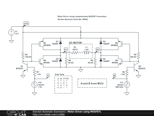
While giving logic signals to the driver, the voltage level from the MCU pin might not be adequate enough. Hence, the BJTs are used as buffers to the input of the MOSFETs. The logic inputs are provided through the two nodes A and B.
When A is 1 and B is 0, transistor Q1 goes to the saturated region and hence acts like a conductor and Q2 goes to the cutoff state. This in turn provides the gates of M1 and M3 with 0 Volts and the gates of M2 and M4 with Vcc. At M1 (p-channel MOSFET), the gate voltage is 0 thus allowing current to pass through M1. At M3 (n-channel MOSFET), the gate voltage is 0 thus allowing no passage of current through M3. At M2 (p-channel MOSFET), the gate voltage is Vcc thus allowing no current to pass through M2. At M4 (n-channel MOSFET), the gate voltage is Vcc thus allowing current to pass through M4. Therefore, the flow of current is from P1 to P2.
Similarly, when A is 0 and B is 1, transistor Q2 goes to the saturated region and hence acts like a conductor and Q1 goes to the cutoff state. This in turn provides the gates of M2 and M4 with 0 Volts and the gates of M1 and M3 with Vcc. At M2 (p-channel MOSFET), the gate voltage is 0 thus allowing current to pass through M2. At M4 (n-channel MOSFET), the gate voltage is 0 thus allowing no passage of current through M4. At M1 (p-channel MOSFET), the gate voltage is Vcc thus allowing no current to pass through M1. At M3 (n-channel MOSFET), the gate voltage is Vcc thus allowing current to pass through M3. Therefore, the flow of current is from P2 to P1.
Now, when A and B are both set to 1, it turns on M1 and M2 thus making P1 and P2 be at the same voltage level, i.e. Vcc. It takes a lot of effort for the motor to turn then and hence is used as a braking mechanism.
The 4 diodes are provided to eliminate the sudden voltage spike which is observed across an inductive load when its supply voltage is suddenly removed. These diodes are known as flyback diodes.